Saturday, December 24, 2011
Holidays with a twist
Have a Merry Christmas everyone, I'll see you next year!
Friday, December 09, 2011
Monday, December 05, 2011
Harper Special
Reading about the Economy tractor made me think about a tractor I saw at Old Threshers this year which was dubbed the "Harper Special." This little mechanical marvel was parked in the truck section with a little sign briefly explaining it's history. Apparently it was built in 1944 by xx Harper who put it together from junkyard scraps and some oak beams back in 1944. The date of construction is actually quite significant. During the war years many things were hard to come by and tractors were no exception. For several years the lend lease program had been sending tractors overseas to support allied farmers so they could keep crop production high enough to feed their armed forces. Then as the US entered the war many factories were re-tooled to produce hardware for tanks, jeeps, artillery and all manner of other military equipment.
It was in the midst of this that Mr. Harper apparently went to the junkyard and gathered together his own kit consisting of a model T engine, two transmissions (one a model T one a 4 speed stick) a rear axle from a truck, A set of wheels (which look suspiciously like something you might find on a manure spreader) and other bits and pieces of equipment.
The result actually has some very clever features. First off, the oak frame seems to have eliminated the need for any significant amount of welding, which probably simplified construction and avoided the need to beg a ration board for steel beams. Model Ts had been around for over 3 decades by this point. There were plenty of them in boneyards to be picked over but they were simple enough to be serviceable and there were enough old Ts still out there that parts were plentiful. The model T engine has an add-on water pump to provide better cooling than the typical buoyancy based circulation. The engine has also been equipped with a governor which is mounted next to the water pump.
Seen here, the governor is connected to the water pump by wooden pulleys. The flyball mechanism works the linkage which actuates the throttle on the carburetor on the opposite side of the engine. The whole thing is connected by linkage back to a lever by the operator.
Also interesting is the use of a dual transmission setup. The model T transmission is really a very simple forerunner of today's automatic gearboxes in that it uses a planetary gear set and bands to provide the forward and reverse gears. The clutch is integrated into transmission and occasional adjustment of the band would keep it in satisfactory condition. By leaving the model T transmission and engine paired together Harper was able to simply use the low gear pedal to engage or disengage the drivetrain. The two forward gear ratios on this transmission also meant that you could drive the tractor in both high or low range. The 4 speed transmission (presumably 3 forward 1 reverse) inline with the first gave the operator a decent selection of gear ratios to work with. Of course it was necessary to mount extensions on the model T pedals so the operator could move them, and the reverse pedal was removed, probably in order to keep someone from putting both transmissions in reverse at the same time and going forward by mistake.
Mr. Harper even planned well enough to add in a PTO pulley by mounting a gearbox (or at least a set of bevel gears) in between the two transmissions.
I doubt I would want to pull very much with this tractor, but I would bet that with the proper hitch mount it could pull a two bottom plow like it's Sears counterpart just so long as the ground was dry enough for the wheels to get decent traction.
Isn't it amazing what can be accomplished with limited materials and a little ingenuity!
Tuesday, November 29, 2011
It's not just a profession,
Yep, planned complete with projected views. It was overkill but it did make me stop and think for a moment.
Engineers in my generation have little to no hand drafting experience. In fact by the time I was in school 2D CAD systems were passed over in favor of 3D modeling, at least in the world of mechanical engineering.
These are very effective tools that give us options nobody would have imagined just 50 years ago including the ability to generate ridiculously complex geometry that can be taken directly to CNC equipment.
The only problem I have with this is that when a computer program can do the heavy work for you it becomes easy to generate designs without having a thorough understanding of the geometry involved. Maybe I just worry too much about these things, but I still think there's something nice about being able to conjur projected views from just a concept and a few construction lines.
Friday, November 18, 2011
Friday, November 11, 2011
Eleventh Hour of the Eleventh Day of the Eleventh Month
Saturday, November 05, 2011
Explosion Motors (In Broad Strokes)
Last time I opened these books I shared some pages on basic 4 stroke engines. This week I’d like show you the section on 2 stroke engines.
Perhaps the biggest advantage of two stroke engines is the simplicity of the design. By using ports in the cylinder wall it is possible to build an engine with one valve or even none at all. The other, perhaps more obvious, advantage is that unlike the 4 stroke Otto cycle design you get a power stroke every revolution, so power tends to be quite good compared to heavy and more complex engines. This is however one of the great weaknesses of this engine types as well, because by condensing the intake, compression, power, and exhaust into half the number of strokes, you end up shortening the power and compression as well as overlapping the intake and exhaust. These changes really cut into your efficiency as high compression and a long power stroke are needed to thoroughly burn fuel. The overlapping of the exhaust and intake also cost some efficiency by allowing fuel to escape through the exhaust port. Add to that the constant flow of engine lubricant through the crankcase to the cylinder and you’ll always have plenty of unburnt oil products blowing out the tailpipe.
Considering all that, it isn’t surprising that two strokes aren’t common in the automotive world. Where they tend to excel is in small handheld tools (blowers, weed whackers, chainsaws, etc) where weight and power are the primary concerns.
The fact that the two stroke appeared so prominently in this text is testament to the fact that in the 1920s people were still very unclear on where the automotive industry was headed. Of course, the American Technical Society was not shy about including extra information in this text. In fact they actually put in a section on aircraft engines.
Brigid mentioned the Antoinette engine in the comments so I did a little looking. I had no success in my old texts, but I did come across a real aerial oddity while I was looking. So, find your white scarf and we’ll take off on a tangent.
This is a Frederickson 70 hp rotary engine. Actually, I should say that again. This is a ROTARY engine, meaning the crankshaft is fixed and the cylinders rotate, unlike a radial engine where the crankshaft turns instead. Having the engine rotate may seem a bit odd, but during the early years of aircraft development this configuration did hold some advantages compared with some of the other options available. This approach could produce a reasonably lightweight design without the need for flywheels or cooling systems. Of course I wouldn’t want to ignore the fact that you were mounting a rather large spinning mass on the front of a light weight machine that has only its wings to provide opposing torque. That’s not necessarily a problem if you only need to turn in one direction, but it’s certainly not conducive to straight and level flight.
Still, rotary engines like the Gnome Monosoupape (single valve) kept much of the early air power aloft.
The Frederickson design is apparently an oddity even for a period rife with
Frederickson took a fairly simple approach and used a sleeve attached to the connecting rod by a swivel.
The lateral motion of the rod (relative to the cylinder) would move this sleeve back and forth, opening a port to admit the fuel air mix when the piston on the compression stroke and seals it on the power stroke thereby compressing the mixture prior to the intake phase. It’s actually quite a neat solution even if it might not be the best for maintenance.
By the time this design was developed, rotary engines were starting to fall behind their radial and inline counterparts. Rapidly improving design and manufacture meant that engines were becoming more reliable and able to rev to higher speeds, while rotary engines encountered dramatically greater wind resistance and higher structural stresses as the rev speeds went up.
Engines like the V8 Hispano Suiza became increasingly popular as did various flavors of radial engines. While the Gnome Monosoupape engine (probably the most common rotary design during the war years) topped out near 150hp, designs like the Hispano Suiza 8 cylinder entered production at 150 horsepower and quickly evolved to models producing well over 200 horses. These provided power for planes like the SE5a and various generations of Spad designs which had a significant impact on the balance of air power in 1917 and 1918.
I’ll start digging for more good tech manual material and see if I can come up with anything interesting for next time.
Sunday, October 23, 2011
Wednesday, October 12, 2011
Explosion Motors!
This is the first of many such posts in which I hope to bring you interesting tidbits from old automotive texts.
It sounds more exciting than saying "Internal Combustion" but that's really what this is talking about. The name died out early in the automotive industry, no doubt to the dismay of steam car builders.
When the American Technical society published their automobile engineering reference in 1920 internal combustion was not particularly new, but the world was still not far removed from the early engines of the 1860s. This is highlighted nicely by the two page explanation of the combustion engine's evolution.
Among the more notable features of this history is the connection between steam engines and 'explosion' engine design. The Lenoir engine mentioned here not only looks considerably like a steam engine, but shares some very functional elements.
Note: not from this manual
Unlike most internal combustion engines, this is a double acting design, meaning that the cylinder is pressurized in both directions (at alternating times of course.) What's more, this is a non compression engine, meaning that that rather than having a combustible mixture drawn into the cylinder, compressed and then ignited, the Lenoir engine simply drew fuel and air into the cylinder, ignited them and allowed them to expand all in one stroke. This action has much more in common with the steam engine than it does with modern combustion applications, and it was short lived in commercial use because of its inefficiency
Moving on to more modern engines, the text explains the 4 stroke engine cycle first put forward by De Rochas and made practical by Otto.
I've seen this illustration in several texts and what I find interesting about it is that it's done using a T head engine, which was rarely seen in use after WWI. It make a very clear illustration of the four stroke cycle, but drawbacks in operation. Mainly, it requires two sets of camshafts and timing chains/gears and it requires a large headspace meaning the compression ratio of the engine will be reduced leading to lower horsepower output. The only real advantage of this design is that it's crossflow layout allows the intake side to be kept cool (typically by a waterjacket) so that the fuel and air drawn into the cylinder are less likely to reach a temperature/pressure ratio that causes early combustion (knocking.) The appearance of leaded gasoline solved most knocking problems and effectively killed this design in favor of L head (flathead) and overhead valve designs.
This section goes on to briefly discuss the concepts of compound gas engines, using the expansion of hot gases and un-burnt fuel for a second, usually larger piston, and double acting gas engines, which essentially require a double ended cylinder.
Both concepts have some theoretical merit but have since been deemed impractical for automotive use due to complexity or unsuitable functionality.
These books are full of interesting plates and lessons, so I'll be posting more excerpts this time next week.
Sunday, October 09, 2011
I smell a series!
He had a six volume set of automotive engineering texts from 1920! After a little negotiating I packed these back to the car and I've been sifting through them ever since. They're too much fun not to share, so I'm taking snapshots of the material so I can put some up from time to time.
This Wed I think "Explosion Motors" will be a good place to start!
Tuesday, September 20, 2011
Where the heck...
Has he been
A - Slowly renovating his old house?
B - Running amok in Southeast Asia?
C - Working in a weekend off during a trip to Australia?
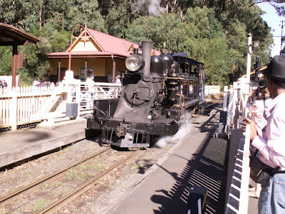
D - Visiting steam and gas engine shows?
E - Attending the Gun Blogger Rendezvous
F - Visiting more steam and gas engine shows
G - That's a lot of stuff, no wonder he hasn't taken the time to post until now!