
I’ll start things off with stationary engines.
The concept behind a stationary steam engine is fairly simple. Steam is generated in a boiler and then piped to an engine where it is used to push a piston down a cylinder. The piston is attached to a push-rod, which turns a crank attached to a flywheel and pulley. Just like that, you have a nice smooth power source to power your machinery.
Not quite.
The problem is, if you just pipe steam into a cylinder, it will push the piston to one end and stop. If you want to push the piston back, you can seal off the other end of the cylinder and pipe steam in on the opposite side of the piston. That’s still not going to help though because if you pipe the same steam pressure to both ends of the cylinder, the pressures cancel each other out and the piston doesn’t move.
What’s really necessary is to make the system work is a set of valves that allow steam to enter one side of the cylinder while allowing it to escape from the other. Unless you want a worker next to the engine all day opening and closing valves, you need a valve gear mechanism.
In its simplest form, a valve gear mechanism is just an eccentric on the crankshaft connected to a pushrod that moves a plate or piston back and forth, that directs the flow of steam and exhaust. This would work for some things, but doesn’t allow the engine to be run efficiently in reverse without stopping to modify the engine setup. After you’ve figured out how to reverse the valve operation there’s another problem.
If you want an engine to run efficiently, you need the ability to adjust the length of time the steam valve is open. Simply leaving the steam valve open for the entire length of a piston’s stroke will give you tremendous power, but it also uses plenty of steam. To reduce the steam consumption, you open the valve briefly at the beginning of the stroke, then shut it again, using the expansion of the steam to move the piston, rather than just the raw pressure supplied from the boiler. Of course the amount of power you need can vary considerably, so it’s necessary to make adjustments to the valve timing while the machine is still running. There are multiple versions of valve gears that deal with this, which were adapted to various applications like steam locomotives and tractors.
After you’ve solved those problems, there’s one more little detail, how do you keep the engine running at the same speed all the time when the load on the machine is being varied constantly? This is where a device called a governor comes into play. It’s a device that creates a feedback loop so that the speed of the engine has an impact on the power applied to each stroke.

In the picture above you will notice a tan belt running from behind the flywheel to a small pulley on the left hand side of the engine. This pulley is geared to something that looks a little like what you’ll see in the next picture.

This is a simple theoretical design. It’s not perfectly accurate to any one device, but it at least similar to what you will see on most steam engines. There are two weights on the end of link arms, and as the assembly rotates, these two weights move further outward until they balance they reach equilibrium with the force supplied by the counterweight. The rod traveling through the middle of the assembly is free to move up and down as the weights and counterbalance push it, and it is this movement that controls the application of power. There are many versions of this type of governor with seemingly endless variations of springs, weights, and linkages, but they all come back to the utilization of centrifugal force on a counterweight.

Even the simplest little engines, like this one, have some sort of governor to control their speed. On this one, you’ll see it located right on top of a valve on the steam supply line.
As always, there are a few more unusual versions of this centrifugal governor design. Here’s an example of an un-restored skinner engine which actually mounts the governor assembly inside the flywheel.

As before, 2 counterweights are spun around and pulled outward from the center of rotation. In this case, they are opposing a force supplied by a large set of leaf springs which are also mounted inside the flywheel. It is also worth noting, that while the previous two examples we’ve seen controlled the engine’s speed by controlling the steam supply, this governor actually changes the motion of the eccentric which controls the amount of travel of the slide valve.
As time went by, the steam engine was refined to get more power for less energy. Valve designs evolved so that valves opened very quickly and precisely in order to get a quick burst of steam into the cylinder, allowing for considerable power at high speeds. As this video shows, there are plenty of moving parts used in some of the more complicated valve systems.
In this case, there two intake valves (located on the top of the cylinder) and two exhaust valves (on the bottom) being driven off of a complex cam system. Two dashpots (seen in the floor) are employed to control the valves as they open and close so that they can be moved quickly with minimal shock.
Another advance in steam engine efficiency was the introduction of double (possibly even triple) expansion steam cylinders.
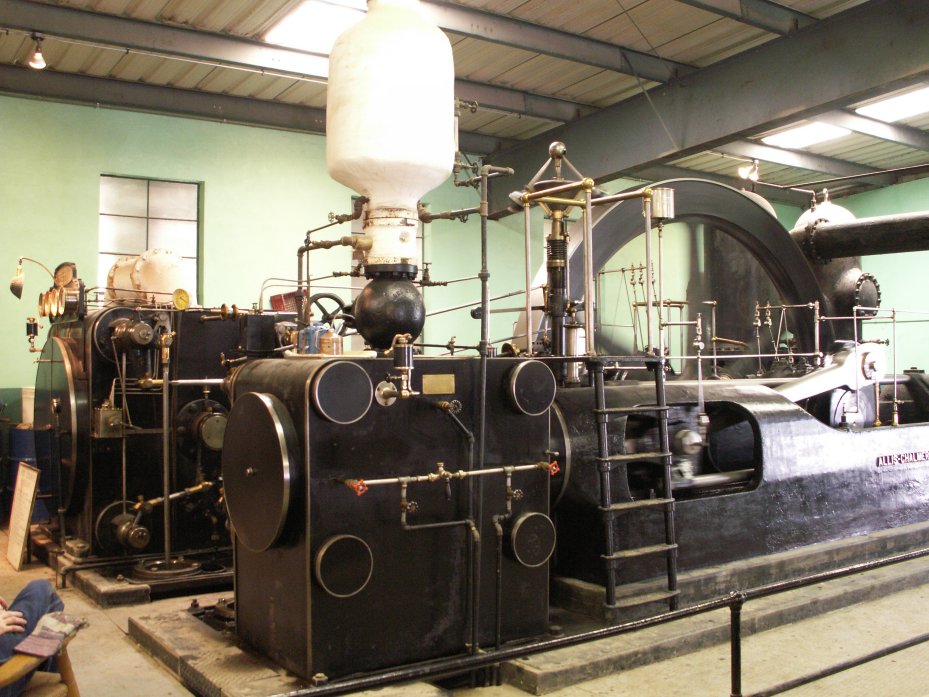
If you look at this picture you’ll notice that this corliss engine, the ‘Marshall’ manufactured by Allis Chalmers, happens to have two cylinders, one of which is much larger than the other. The reason for this is that even after a quantity of steam is used once, it usually has some remaining potential for expansion. The problem is, this ‘used steam’ occupies a much greater volume than it did originally and it provides much lower pressure than before, so in order to get similar amounts of force, you need to have a larger surface area for it to push against. With this in mind, you can understand how it is appropriate to first send steam to the small cylinder and then send the exhaust from that cylinder to the larger cylinder.
This increases efficiency by getting more energy out of a given quantity of steam, but it also adds considerably to the complexity of the machine. I think this is best illustrated by this next picture.

I really love that view of the engine because most of the parts you see in the picture are moving, so watching it run is quite impressive.
Eventually these beautiful behemoths would be replaced by other power sources, but that doesn’t mean they become any less interesting.
1 comment:
Complex control systems using valves requires an automatic control based input of an actuator. The actuator strokes the valve allowing the valve to be positioned accurately and allowing control over a variety of requirements.
Post a Comment